Practical LED Light Measurement
Solid state lighting employing Light-Emitting Diodes (LEDs) is evolving and transforming the entire world of lighting. Tremendous progress in the development of functional high efficiency high power white LEDs has made it possible to employ them in general lighting fixtures replacing traditional bulb and other type lamps. An LED luminaire or fixture is constructed by combining many single LEDs in a matrix configuration. Since the human eye is extremely sensitive to differences in color and intensity of lighting devices when placed side by side, tolerances in intensity and color temperature become critical. This article describes measurement technologies and quantities useful for LED qualification as well as the description of a LED lightmeter for industrial use.
The low tolerance variations required LED manufacturers to respond by improved processing technologies and compensation for any remaining differences caused by the sorting and binning of the LEDs. Due to the high volume production demands the measurement process had to be fast with the LED under test under operation for only a few milliseconds. As with any light source the LED light and color specifications are effected by operating temperature. That's why for best accuracy the light source under test is burned-in to a stable operating temperature before measurement. In the LED sorting measurement process which lasts only a few milliseconds per LED the junction and phosphor temperature of blue LED stimulated white LEDs will be much cooler as compared to the operation temperature in the actual application. This difference between sorting test and operation temperature seems to be the reason that upon visual inspection unacceptable variations in the finished assembled LED matrix are noticed. Since high volume LED sorting by the manufacturer cannot be done under real operation conditions the LED processing industry requires measurement technology that supports sorting and qualification at the implementation stage.
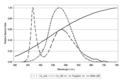
Traditional light and luminous color meters are built with photometric V(λ) and colorimetric RGB filtered detectors. The spectral response of these detectors are made to match the CIE and DIN standardized V(λ), Y(λ) and Z(λ) spectral functions as close as possible. For decades the filter photometer has been the basic tool for all kinds of light measurement applications in research and industry. Filter photometers and luminous color meters are typically calibrated with CIE Standard Illuminant A calibration lamps which are tungsten halogen lamps operated at 2856°K. Test light sources with a similar broadband, continuous with low blue spectral content emission spectra can be measured using the filter photometer with acceptable measurement uncertainties. However, measurement uncertainties increase significantly for light sources with a different spectral distribution than the calibration source like fluorescence tube lamps (FTL) and compact fluorescence lamps (CFL) which have higher blue spectral content. This is due to the filter photometer spectral mismatch error. Quasi-monochromatic LEDs and blue LED stimulated white LED emission spectra are totally different than that of the calibration source and may create further unknown increases in measurement uncertainty. Note that filter photometers are still widely used and do an excellent job when properly specified and applied. Plus their large linear dynamic range and fast response time makes them irreplaceable for several applications.
Current state of the art LED intensity and color measurement devices employ spectral measurement technology. This type of instrumentation falls into the three categories: scanning grating monochromator spectroradiometer, diode array spectrometer and BiTec™ light analyzer.
Scanning grating monochromators represent the high end in light measurement instrumentation due to their excellent monochromatic light separation capability with low stray light ratio. The absolute intensity and color properties are calculated using the spectral data measured. This type of spectral radiometer is usually not portable, slow, expensive and complex and therefore not practical for regular everyday industrial applications. They are normally used as reference measurement devices in calibration laboratories and in research & development.
Diode array spectrometers, the alternative spectral measurement method offers fast one shot measurement of light source emission spectra. But they have limitations in absolute scale light measurements due to inherent pixel non-linearity effects and monochromatic separation is not as good as the grating monochromator due to stray light. These effects can be reduced to acceptable levels but only through extraordinary measures in the form of active array cooling, dark signal compensation with electro-optical shutters and other methods. Beside the added cost aspect these add-ons increase the instrument footprint and power consumption which then restricts their use to stationary set-ups like the grating spectral radiometer.
The third and newest category is the BiTec™ sensor which combines a diode array spectrometer with a fast high precision filtered photometric detector. This method exploits each sensor technology's advantages and compensates for each technology's inherent shortcomings. Light intensity is measured with the photometric filter detector and the spectral data with the diode array spectrometer. Both sensors are mounted onto a small integrating sphere so no light guide is needed making it a hand-held and portable meter. The integration time dependent pixel offset signal of the diode array limits the signal to noise ratio and therefore the quality of spectral and color readings. A kinetic remote shutter for on-line offset compensation without the need for active array cooling helps compensate for this effect.
The applicable measurement type and associated units are just as important as the measurement technology in LED qualification.
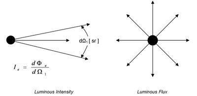
Luminous intensity is a common measurement employed by LED manufacturers. Luminous intensity quantifies the luminous flux emitted by a source in a certain direction and is measured in lumens per solid angle or candela (cd). A uniform light distribution is assumed. To comply with photometric principles the measurement distance between source and detector must be at least 10 times the maximum dimension of the source. In practice the measurement is complicated due to the need for precise distancing and axial alignment of the detector in front of the LED test sample. Be aware that the manufacturer luminous intensity specifications can only be reproduced if the measurement geometries are identical or if the LED exhibits a uniform spatial flux distribution. If the flux pattern is not uniform the total flux cannot be calculated using the luminous intensity data. Different solid angles during the measurement may also affect differences in the color data because of typical LED color variation in certain directions.
Luminous flux measured in lumens is the basic photometric quantity and describes the total amount of light emitted by a source. It therefore precisely indicates the LED efficiency in electrical power to luminous flux ratio so it is used as the control parameter for color data under different operating conditions. Total flux measurement is a practical and repeatable type of measurement for the qualification of single unassembled LEDs, single mounted LEDs, LED arrays and lensed LEDs.
For well collimated parallel beam sources total flux can be measured using a flat planar photo detector with an active area larger than that of the beam diameter. But since most LED sources emit in a divergent beam or in a hemispherical pattern different measurement set-ups are required to capture the emitted light from all directions.
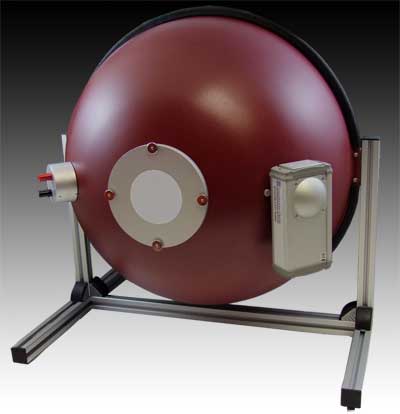
The most common device used to capture total flux for measurement is the integrating sphere. It is comprised of a hollow sphere that produces a uniform light density distribution on its internal spherical surface that is independent of the incoming light source spatial emission distribution. As a result a detector mounted on the sphere will detect the integral of the omni-directional flux. This is only a simplification of the sphere operating principle. In practice integrating sphere and sphere system designs can become complex based on the individual application. One of the main design criteria of an integrating sphere is its size which depends mainly on the size of the source to be measured. The sphere should be large enough so that any error effects from internal baffles and test sample self-absorption errors are minimized. On the other hand since sphere size is directly related to attenuation level small size spheres are preferable when low flux light sources such as LEDs powered operated with low currents need to be measured. One other important design criteria is the self-absorption effect caused by the test sample itself placed at the sphere measurement port or inside the sphere. Light throughput and therefore the sensitivity of the measurement device can change up to several percent due to this effect adding more measurement uncertainty. Auxiliary lamps mounted on the sphere are essential for correction of any self-absorption effects.
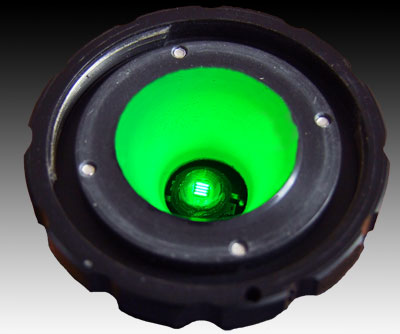
For single LEDs the CIE recommends a minimum 200mm diameter integrating sphere detection system. By performing alternative calibrations of the sphere system much smaller sphere diameters down to 50mm can be used. The LED must be inserted into the measurement port of the integrating sphere so that all light emitted enters the sphere. For flux and color measurement of assembled LEDs a cone adapter which in effect stretches the sphere can be placed over the LED to isolate it for measurement and avoiding conflict with other components assembled around the test device. The measurement port size of the sphere should be small in relation to the sphere diameter to limit light loss and disruption of the light distribution within the hollow sphere.
Illuminance measured in lux is a simple way to qualify a finished LED luminaire. Illuminance information is also useful for architects and lighting designers who need to know the level of available light incident on a surface at some distance away from the light source. If the luminaire can be considered a point source where the largest source dimension is ten times the source to detection distance then the illuminance readings can be used to calculate candlepower. Spectral measurement devices which can also deliver color information are being used more in illuminance applications for better accuracy when testing different types of light sources and LEDs.
Where the spatial light distribution characteristic is important goniometric measurement set-ups are used. Calibrated systems can measure in absolute units like angular luminous intensity distribution for example. The total flux can then be calculated by the summing the luminous intensity distribution values. The typical goniometric measurement set-up for LEDs is built with two rotary tables supporting the orientation of the test LED in Phi and Theta axes to the detector. The detector size and the distance between LED and detector form the solid angle in which the luminous intensity is measured. Because of the mechanical drive systems and the need to stop and take a measurement at each angle goniometric measurement devices are slow and expensive. Goniometers are typically used if spatial distribution data is an essential quality control factor, for example to qualify the light beam profile of luminaires that must direct light in a certain direction like street or parking lot lighting.
Measuring LED Color properties is a high priority in the production of LED fixtures. Most LED manufacturer datasheets will include color data like color coordinates, color temperature, color rendering index (CRI), color purity or color deviation. As stated earlier, color is most accurately measured with a spectral measurement instrument. The various color properties are calculated using the measured spectral data. But once assembled into the fixture the individual LED color specs could change causing a noticeable variation in color within the luminaire. For white LEDs the critical color parameters for matching are color temperature and CRI. Slight variations in color temperature will create an uneven lighting effect. In display or accent lighting the white LED is highly desirable for clean lighting but if the CRI is not optimal this type of lighting can detract from the subject appearance. Often at the implementation stage it is more beneficial and practical to qualify the LEDs relative to each other rather than in absolute terms.
In LED implementation applications if only one type of measurement instrument could be chosen it would be a luminous flux and color meter with illuminance capability option.
This type of meter can support LED qualification through all the different phases of production including measurement of:
- Single unassembled LEDs for incoming inspection and sorting purposes
- Single assembled LEDs to detect any changes due to the soldering process and the heat sink effect of the pc board
- LED arrays before assembly into the luminaire
- Single LEDs or LED arrays with front lens or optics to measure the influence and efficiency of the optic
- If illuminance data needs to be supplied with the final LED luminaire a qualified LED luxmeter would be needed
For increased flexibility modular light meters that enable accessories to be attached and interchanged such as different size integrating spheres and illuminance diffusers help to reduce instrumentation costs.
Technical Sales Engineer
Full Time, Amesbury, MA, USA
Gigahertz-Optik Inc. is looking for a Technical Sales/Application Engineer for our innovative measurement instrumentation products.
Contact info-us@gigahertz-optik.com for details.